|     


METAL INJECTION MOLDING PROCESS

MIM offers a manufacturing capability for mass producing complex shaped metal parts consistently and reliably.
The advantages of the MIM process lie in its capability to produce excellent components with mechanical properties, while being a net-shape process technology with good dimensional tolerance control. MIM parts offer a nearly unlimited shape and geometric-feature capability, with high-production rates possible using multi-cavity tooling.

The Metal Powder Industries Federation’s (MPIF) Industry Development Board created a video that provides an overview of metal injection molding.

The following is an overview of the metal injection molding process.


STEP ONE: FEEDSTOCK MIXING AND GRANULATING

The first step in the MIM manufacturing process is the production of the feedstock that will be used. It begins with extensive characterization of very fine elemental or prealloyed metal powders (generally less than 30 micrometre). In order to achieve the flow characteristics that will be required in the injection molding process, the powder is mixed together with a binder (various thermoplastic polymers, waxes, and other materials) in a hot state in order to form a mixture in which every metal particle is uniformly coated with the binder. This mixture is then granulated into pellets to form the feedstock for the injection molding machine. Typically, binders comprise 40% by volume of the feedstock.


STEP TWO: MOLDING

The next step is the molding of the part in a conventional injection molding machine. The feedstock pellets are gravity fed from a hopper into the molding machine where the heated barrel combined with the shear imparted by the screw, bring the feedstock to a toothpaste like consistency. A reciprocating screw forces the material into a two-part mold through openings called gates. Once cooled, the part is ejected from the mold with its geometry fully formed. At this stage the part is called a “green” part. The green part is still composed of the same proportion of metal powder and binder that made up the feedstock, and is approximately 20% larger (binder volume dependent) in all its dimensions than the finished part will be. If necessary, additional design features not feasible during the molding process (undercuts or cross holes, for example) can be easily added at this stage by machining or another secondary operation.


STEP THREE: FIRST STAGE BINDER REMOVAL

The next step is to remove most of the first stage binder, leaving behind the secondary binder to serve as a backbone holding the size and geometry of the part completely intact. This process, commonly referred to as “debinding,” may be performed via a catalytic, a solvent or water bath, or thermal debinding step. The choice of debinding method is tied to the original decision of which feedstock type to use. After debinding, the part is referred to as a “brown part.”


STEP FOUR: SECOND STAGE BINDER REMOVAL AND SINTERING

In this process, which is performed in the highly controlled atmosphere of either a batch furnace or a continuous furnace, the brown part is staged on a ceramic or graphite “setter” and is then subjected to a precisely monitored temperature profile that gradually increases to approximately 85% of the metal’s melting temperature. The remaining binder is removed in the early part of this sintering cycle, followed by the elimination of pores and the fusing of the metal particles as the part shrinks isotropically to its design dimensions and transforms into a dense solid.

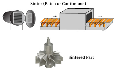
Sintering is commonly done either at a temperature which is slightly below the liquidus/solidus temperature of the alloy, or slightly above the liquidus temperature of the alloy. This is called solid-state sintering or liquid-state sintering respectively, which is either the part’s solidus temperature which is nearly high enough to induce partial melting in a process termed liquid-phase sintering. For example, a stainless-steel part might be heated to 1,350 to 1,400 degrees Celsius. Diffusion rates are high leading to high shrinkage (typically 18%–22%, binder volume dependent) and densification. If performed in a controlled atmosphere, it is common to reach 96%–99% of the theoretical density. The end-product metal has mechanical and physical properties similar to annealed parts made using conventional metalworking methods.

The end result is a net-shape or near-net-shape metal component, with properties similar to those of one machined from bar stock. When necessary, secondary operations such as coining, machining, heat treating, coating, and others, may be performed on the part to achieve tighter tolerances or enhanced properties.


WHAT CAN BE MADE WITH METAL INJECTION MOLDING?

Explore how metal injection molding meets or exceeds customer expectations through component case studies. MIM components are used through the medical & dental, aerospace, defense, automotive, and agricultural markets, among others.


VIEW CASE STUDIES


Find a Supplier or Fabricator


Whether you’re looking for a powder or feedstock supplier, an equipment provider or a fabricator of MIM components, our member directory has you covered. Explore our searchable directory of Metal Injection Molding Association Members to find the right company to fit your needs.
 

EXPLORE OUR DIRECTORY

Our Family of Websites


                   ​ ​​​​​​