Coring Holes
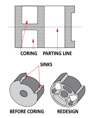 Cored holes can be used to
reduce cross sections to within guideline limits, achieve uniform wall thickness, reduce material
consumption, and reduce or eliminate machining operations. As shown in Figure 1, the preferred direction is
parallel to the direction of the mold opening, in other words, perpendicular to the parting plane. Through
holes are preferred to blind holes when the length/diameter ratio is greater than 4:1 because the core pin
is supported on both ends, whereas blind holes use a cantilevered pin.
Cored holes can be used to
reduce cross sections to within guideline limits, achieve uniform wall thickness, reduce material
consumption, and reduce or eliminate machining operations. As shown in Figure 1, the preferred direction is
parallel to the direction of the mold opening, in other words, perpendicular to the parting plane. Through
holes are preferred to blind holes when the length/diameter ratio is greater than 4:1 because the core pin
is supported on both ends, whereas blind holes use a cantilevered pin.
Decorative Features
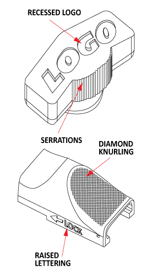 Features such as logos, knurls,
part numbers, and cavity identification marks can be easily molded in place, without added cost to the piece
price. These features can be either raised or sub-surface. MIM can provide high levels of feature detail,
including relatively sharp diamond knurling.
Features such as logos, knurls,
part numbers, and cavity identification marks can be easily molded in place, without added cost to the piece
price. These features can be either raised or sub-surface. MIM can provide high levels of feature detail,
including relatively sharp diamond knurling.
Draft
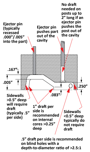 Draft is the small angle on
surfaces that would otherwise be parallel to the direction of movement of mold members. This is particularly
true for core pins. Draft is provided to facilitate the release and ejection of the molded form. The normal
range is 0.5° to 2.0°. As the length of the component element becomes longer of if the surface is textured,
a greater draft should be used. As shown in Figure 2 shows some of the circumstances that require draft.
Draft is the small angle on
surfaces that would otherwise be parallel to the direction of movement of mold members. This is particularly
true for core pins. Draft is provided to facilitate the release and ejection of the molded form. The normal
range is 0.5° to 2.0°. As the length of the component element becomes longer of if the surface is textured,
a greater draft should be used. As shown in Figure 2 shows some of the circumstances that require draft.
Fillets and Radii
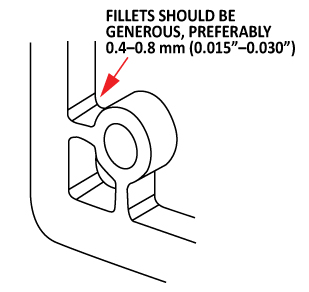 Fillets and radii are generally
advantageous to product function as they reduce stresses at the intersection of features. They are also
advantageous to the molding process, by eliminating sharp corners that can cause cracking or erosion of mold
features, by facilitating the flow of feedstock into the mold, and by assisting in the ejection of the part
from the cavity. They may also provide a softening of sharp corners for esthetics and handling. Fillets and
radii of 0.4–0.8 mm (0.015–0.030 in.) are generally preferred.
Fillets and radii are generally
advantageous to product function as they reduce stresses at the intersection of features. They are also
advantageous to the molding process, by eliminating sharp corners that can cause cracking or erosion of mold
features, by facilitating the flow of feedstock into the mold, and by assisting in the ejection of the part
from the cavity. They may also provide a softening of sharp corners for esthetics and handling. Fillets and
radii of 0.4–0.8 mm (0.015–0.030 in.) are generally preferred.
Gating
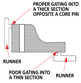 Feedstock enters the mold cavity
through an opening called a “gate”; due to the high metals loading of MIM feedstock, these openings are
generally much larger for MIM than for plastic injection molding. Because gates usually leave a mark on the
finished part where they are separated from the molded form, locating them involves balancing the demands of
manufacturability, function, dimensional control, and esthetics. As shown in Figure 3, gates are generally
best located on the parting line of the mold, positioned so the flow path impinges on a cavity wall or a
core pin. There are other considerations for gate locations, such as subgates, tunnel gates, or pin point
gates. for a component with different wall thicknesses, it is usually placed at the thickest cross section
so the material flows from thick to thin section. Such a placement reduces voids, sink marks, stress
concentrations, and flow lines on the part surface. If the part will be produced in multiple cavities, added
consideration must be given to gate size and placement to assure that an identical amount is delivered to
each cavity at a balanced fill rate.
Feedstock enters the mold cavity
through an opening called a “gate”; due to the high metals loading of MIM feedstock, these openings are
generally much larger for MIM than for plastic injection molding. Because gates usually leave a mark on the
finished part where they are separated from the molded form, locating them involves balancing the demands of
manufacturability, function, dimensional control, and esthetics. As shown in Figure 3, gates are generally
best located on the parting line of the mold, positioned so the flow path impinges on a cavity wall or a
core pin. There are other considerations for gate locations, such as subgates, tunnel gates, or pin point
gates. for a component with different wall thicknesses, it is usually placed at the thickest cross section
so the material flows from thick to thin section. Such a placement reduces voids, sink marks, stress
concentrations, and flow lines on the part surface. If the part will be produced in multiple cavities, added
consideration must be given to gate size and placement to assure that an identical amount is delivered to
each cavity at a balanced fill rate.
Holes and Slots
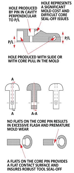 Besides being used to reduce
part mass and provide uniform wall thicknesses, holes and slots can provide useful functional features in
MIM components, and can generally be produced without adding to the piece price. However, adding these
features does increase the complexity of the mold, as shown in Figure 4a, which potentially adds to its
cost. Holes that are perpendicular to the parting line are the easiest (and least costly) to mold in. Holes
that are located parallel to the parting line, while readily achievable, require mechanical slides or
hydraulic cylinders, which increases the up-front tooling costs. Internally connected holes are possible, as
shown in Figure 4b. To prevent potential sealing-off problems and issues with flashing, careful
consideration must be given to the design. If possible, one hole should be D-shaped in order to provide a
flat on the core pin for a robust tool seal-off, as well as to eliminate inordinate wear of the feathered
edges that would otherwise be required on the contoured face of the mating member.
Besides being used to reduce
part mass and provide uniform wall thicknesses, holes and slots can provide useful functional features in
MIM components, and can generally be produced without adding to the piece price. However, adding these
features does increase the complexity of the mold, as shown in Figure 4a, which potentially adds to its
cost. Holes that are perpendicular to the parting line are the easiest (and least costly) to mold in. Holes
that are located parallel to the parting line, while readily achievable, require mechanical slides or
hydraulic cylinders, which increases the up-front tooling costs. Internally connected holes are possible, as
shown in Figure 4b. To prevent potential sealing-off problems and issues with flashing, careful
consideration must be given to the design. If possible, one hole should be D-shaped in order to provide a
flat on the core pin for a robust tool seal-off, as well as to eliminate inordinate wear of the feathered
edges that would otherwise be required on the contoured face of the mating member.
Parting Lines
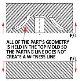 The parting line is the plane in
which the two halves of the mold meet. To the extent possible, all features should be oriented perpendicular
to the parting line to facilitate removal from the mold. Normally, the parting line is transferred to the
surface of the part as a witness line, an unavoidable result of two mating mold members. In some cases, as
in the example shown in Figure 5, the full part geometry can be maintained in the ejector side or “B” side
of the mold, in which case the parting line would be along the bottom edge of the component and no witness
line would be created. At other times, the mold may be designed to separate along an inconspicuous edge,
thus “hiding” the parting line. A parting line that can be contained in a single plane is preferred.
However, it is sometimes necessary to modify the simple shape in order to mold desirable features. The added
complexity, although it increases the cost of fabricating and maintaining the tools, may be cost effective
when the features it molds would otherwise require machining or assembly operations.
The parting line is the plane in
which the two halves of the mold meet. To the extent possible, all features should be oriented perpendicular
to the parting line to facilitate removal from the mold. Normally, the parting line is transferred to the
surface of the part as a witness line, an unavoidable result of two mating mold members. In some cases, as
in the example shown in Figure 5, the full part geometry can be maintained in the ejector side or “B” side
of the mold, in which case the parting line would be along the bottom edge of the component and no witness
line would be created. At other times, the mold may be designed to separate along an inconspicuous edge,
thus “hiding” the parting line. A parting line that can be contained in a single plane is preferred.
However, it is sometimes necessary to modify the simple shape in order to mold desirable features. The added
complexity, although it increases the cost of fabricating and maintaining the tools, may be cost effective
when the features it molds would otherwise require machining or assembly operations.